GM to Section 2, Chapter 3 Performance class 2
CAA ORS9 Decision No. 1
OPERATIONS IN PERFORMANCE CLASS 2
(a) Introduction
This GM describes performance class 2 as established in Part-CAT. It has been produced for the purpose of:
(1) explaining the underlying philosophy of operations in performance class 2;
(2) showing simple means of compliance; and
(3) explaining how to determine — with examples and diagrams:
(i) the take-off and landing masses;
(ii) the length of the safe forced landing area;
(iii) distances to establish obstacle clearance; and
(iv) entry point(s) into performance class 1.
It explains the derivation of performance class 2 from ICAO Annex 6 Part III and describes an alleviation that may be approved in accordance with CAT.POL.H.305 following a risk assessment.
It examines the basic requirements, discusses the limits of operation, and considers the benefits of the use of performance class 2.
It contains examples of performance class 2 in specific circumstances, and explains how these examples may be generalised to provide operators with methods of calculating landing distances and obstacle clearance.
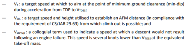
(b) Definitions used in this GM
The definitions for the following terms, used in this GM, are contained in Annex I and its AMC:
(1) distance DR;
(2) defined point after take-off (DPATO);
(3) defined point before landing (DPBL);
(4) landing distance available (LDAH);
(5) landing distance required (LDRH);
(6) performance class 2;
(7) safe forced landing (SFL); and
(8) take-off distance available (TODAH).
The following terms, which are not defined Annex I, are used in this GM:
(c) What defines performance class 2
Performance class 2 can be considered as performance class 3 take-off or landing, and performance class 1 climb, cruise and descent. It comprises an all-engines-operating (AEO) obstacle clearance regime for the take-off or landing phases, and a OEI obstacle clearance regime for the climb, cruise, descent, approach and missed approach phases.
For the purpose of performance calculations in Part-CAT, the CS/JAR 29.67 Category A climb performance criteria is used:
at the appropriate power settings.
(1) Comparison of obstacle clearance in all performance classes
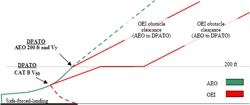
Figure 1 shows the profiles of the three performance classes — superimposed on one diagram.
— Performance class 1 (PC1): from TDP, requires OEI obstacle clearance in all phases of flight; the construction of Category A procedures, provides for a flight path to the first climb segment, a level acceleration segment to Vy (which may be shown concurrent with the first segment), followed by the second climb segment from Vy at 200 ft (see Figure 1).
Figure 1: All Performance Classes (a comparison)
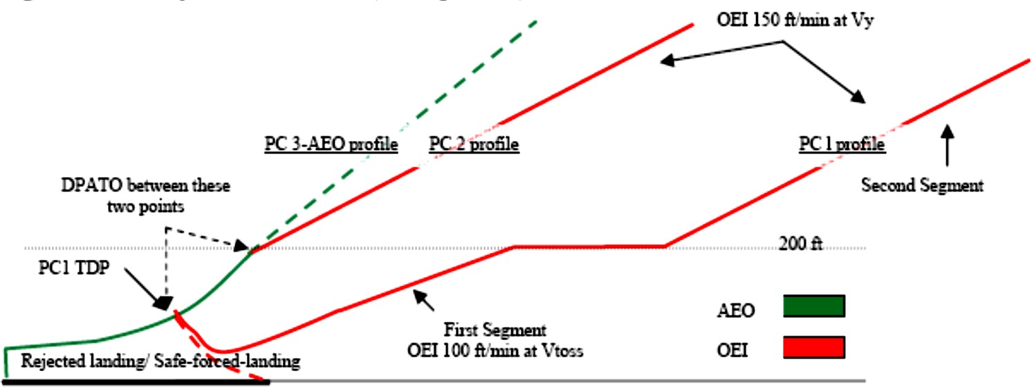
— Performance class 2 (PC2): requires AEO obstacle clearance to DPATO and OEI from then on. The take-off mass has the PC1 second segment climb performance at its basis therefore, at the point where Vy at 200 ft is reached, Performance Class 1 is achieved (see also Figure 3).
— Performance class 3 (PC3): requires AEO obstacle clearance in all phases.
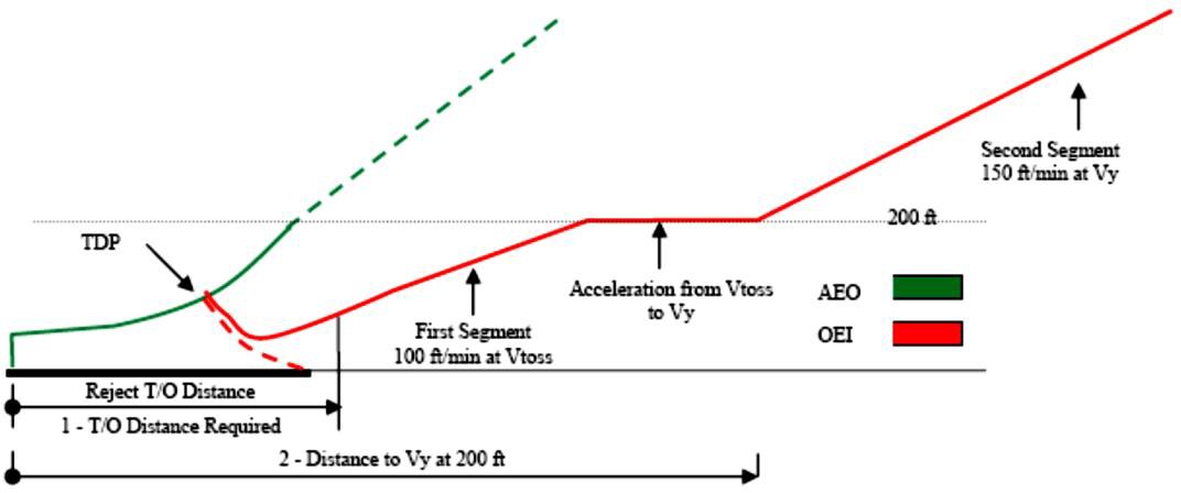
Figure 2: Performance Class 1 distances
(2) Comparison of the discontinued take-off in all performance classes
(i) PC1 — requires a prepared surface on which a rejected landing can be undertaken (no damage); and
(ii) PC2 and 3 — require a safe forced landing surface (some damage can be tolerated, but there must be a reasonable expectancy of no injuries to persons in the aircraft or third parties on the surface).
(d) The derivation of performance class 2
PC2 is primarily based on the text of ICAO Annex 6 Part III Section II and its attachments which provide for the following:
(1) obstacle clearance before DPATO: the helicopter shall be able, with all engines operating, to clear all obstacles by an adequate margin until it is in a position to comply with (2);
(2) obstacle clearance after DPATO: the helicopter shall be able, in the event of the critical engine becoming inoperative at any time after reaching DPATO, to continue the take-off clearing all obstacles along the flight path by an adequate margin until it is able to comply with en-route clearances; and
(3) engine failure before DPATO: before the DPATO, failure of the critical engine may cause the helicopter to force land; therefore, a safe forced landing should be possible (this is analogous to the requirement for a reject in performance class 1, but where some damage to the helicopter can be tolerated.)
(e) Benefits of performance class 2
Operations in performance class 2 permit advantage to be taken of an AEO procedure for a short period during take-off and landing — whilst retaining engine failure accountability in the climb, descent and cruise. The benefits include the ability to:
(1) use (the reduced) distances scheduled for the AEO — thus permitting operations to take place at smaller aerodromes and allowing airspace requirements to be reduced;
(2) operate when the safe forced landing distance available is located outside the boundary of the aerodrome;
(3) operate when the take-off distance required is located outside the boundary of the aerodrome; and
(4) use existing Category A profiles and distances when the surface conditions are not adequate for a reject, but are suitable for a safe forced landing (for example, when the ground is waterlogged).
Additionally, following a risk assessment when the use of exposure is approved by the CAA the ability to:
(i) operate when a safe forced landing is not assured in the take-off phase; and
(ii) penetrate the HV curve for short periods during take-off or landing.
(f) Implementation of performance class 2 in Part-CAT
The following sections explain the principles of the implementation of performance class 2.
(1) Does ICAO spell it all out?
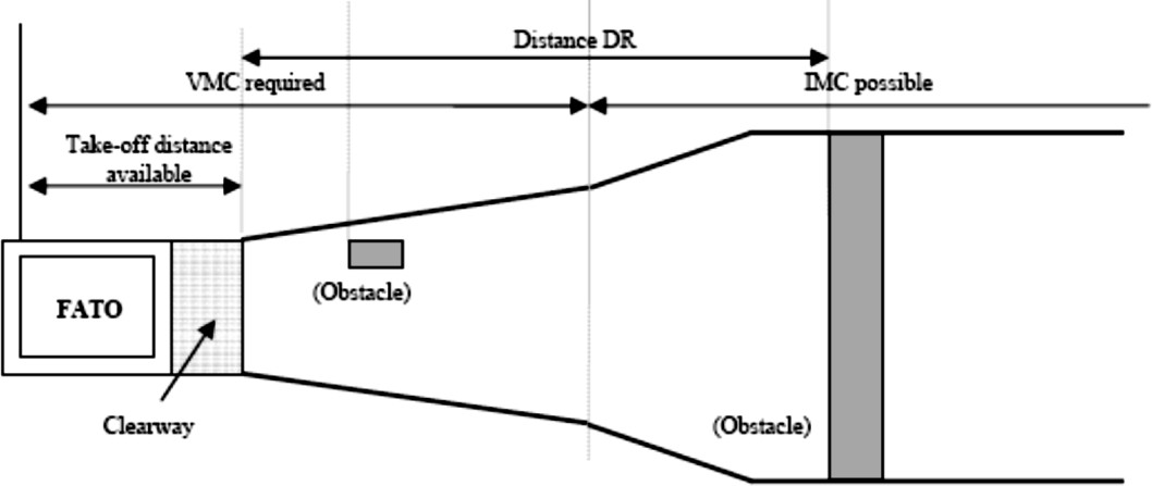
ICAO Annex 6 does not give guidance on how DPATO should be calculated nor does it require that distances be established for the take-off. However, it does require that, up to DPATO AEO, and from DPATO OEI, obstacle clearance is established (see Figure 3 and Figure 4 which are simplified versions of the diagrams contained in Annex 6 Part III, Attachment A).
(ICAO Annex 8 – Airworthiness of Aircraft (IVA 2.2.3.1.4’ and ‘IVB 2.2.7 d) requires that an AEO distance be scheduled for all helicopters operating in performance classes 2 & 3. ICAO Annex 6 is dependent upon the scheduling of the AEO distances, required in Annex 8, to provide data for the location of DPATO.)
When showing obstacle clearance, the divergent obstacle clearance height required for IFR is — as in performance class 1 — achieved by the application of the additional obstacle clearance of 0.01 distance DR (the distance from the end of ‘take-off-distance- available’ — see the pictorial representation in Figure 4 and the definition in Annex I).
As can also be seen from Figure 4, flight must be conducted in VFR until DPATO has been achieved (and deduced that if an engine failure occurs before DPATO, entry into IFR is not permitted (as the OEI climb gradient will not have been established)).
Figure 3: Performance Class 2 Obstacle Clearance (plan view)
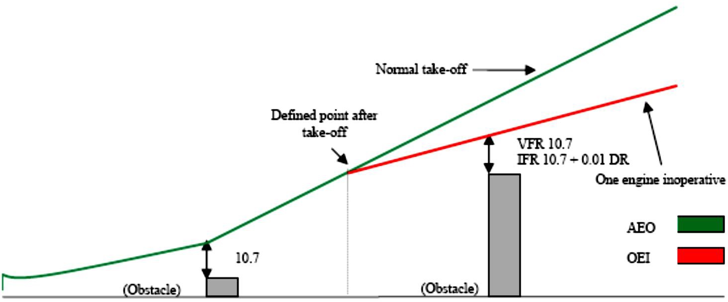
Figure 4
(2) Function of DPATO
From the preceding paragraphs, it can be seen that DPATO is germane to PC2. It can also be seen that, in view of the many aspects of DPATO, it has, potentially, to satisfy a number of requirements that are not necessarily synchronised (nor need to be).
It is clear that it is only possible to establish a single point for DPATO, satisfying the requirement of (d)(2) & (d)(3), when:
— accepting the TDP of a Category A procedure; or
— extending the safe forced landing requirement beyond required distances (if data are available to permit the calculation of the distance for a safe forced landing from the DPATO).
It could be argued that the essential requirement for DPATO is contained in section (d)(2) — OEI obstacle clearance. From careful examination of the flight path reproduced in Figure 3 above, it may be reasonably deduced that DPATO is the point at which adequate climb performance is established (examination of Category A procedures would indicate that this could be (in terms of mass, speed and height above the take-off surface) the conditions at the start of the first or second segments — or any point between.)
(The diagrams in Attachment A of ICAO Annex 6 do not appear to take account of drop down — permitted under Category A procedures; similarly with helideck departures, the potential for acceleration in drop down below deck level (once the deck edge has been cleared) is also not shown. These omissions could be regarded as a simplification of the diagram, as drop down is discussed and accepted in the accompanying ICAO text.)
It may reasonably be argued that, during the take-off and before reaching an appropriate climb speed (VTOSS or Vy), Vstayup will already have been achieved (where Vstayup is the ability to continue the flight and accelerate without descent — shown in some Category A procedures as VT or target speed) and where, in the event of an engine failure, no landing would be required.
It is postulated that, to practically satisfy all the requirements of (d)(1), (2) and (3), DPATO does not need to be defined at one synchronised point; provisions can be met separately, i.e. defining the distance for a safe forced landing, and then establishing the OEI obstacle clearance flight path.
As the point at which the helicopter’s ability to continue the flight safely, with the critical engine inoperative is the critical element, it is that for which DPATO is used in this text.
Figure 5: The three elements in a PC 2 take-off
The three elements from the pilot’s perspective
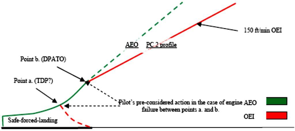
When seen from the pilot’s perspective (see Figure 5), there are three elements of the PC 2 take-off — each with associated related actions which need to be considered in the case of an engine failure:
(A) action in the event of an engine failure — up to the point where a forced-landing will be required;
(B) action in the event of an engine failure — from the point where OEI obstacle clearance is established (DPATO); and
(C) pre-considered action in the event of an engine failure — in the period between (A) and (B)
The action of the pilot in (A) and (B) is deterministic, i.e. it remains the same for every occasion. For pre-consideration of the action at point (C), as is likely that the planned flight path will have to be abandoned (the point at which obstacle clearance using the OEI climb gradients not yet being reached), the pilot must (before take-off) have considered his/her options and the associated risks, and have in mind the course of action that will be pursued in the event of an engine failure during that short period. (As it is likely that any action will involve turning manoeuvres, the effect of turns on performance must be considered.)
(3) Take-off mass for performance class 2
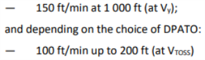
As previously stated, performance class 2 is an AEO take-off that, from DPATO, has to meet the requirement for OEI obstacle clearance in the climb and en-route phases. Take- off mass is, therefore, the mass that gives at least the minimum climb performance of 150 ft/min at Vy, at 1 000 ft above the take-off point, and obstacle clearance.
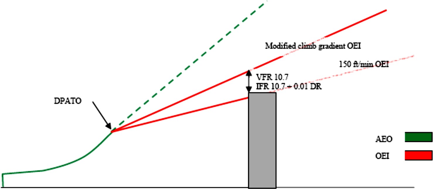
As can be seen in Figure 6 below, the take-off mass may have to be modified when it does not provide the required OEI clearance from obstacles in the take-off-flight path (exactly as in performance class 1). This could occur when taking off from an aerodrome/operating site where the flight path has to clear an obstacle such a ridge line (or line of buildings) that can neither be:
(i) flown around using VFR and see and avoid; nor
(ii) cleared using the minimum climb gradient given by the take-off mass (150 ft/min at 1 000 ft).
In this case, the take-off mass has to be modified (using data contained in the AFM) to give an appropriate climb gradient.
Figure 6: Performance Class 2 (enhanced climb gradient)
(4) Do distances have to be calculated?
Distances do not have to be calculated if, by using pilot judgement or standard practice, it can be established that:
(i) a safe forced landing is possible following an engine failure (notwithstanding that there might be obstacles in the take-off path); and
(ii) obstacles can be cleared (or avoided) — AEO in the take-off phase and OEI in the climb.
If early entry (in the sense of cloud base) into IMC is expected, an IFR departure should be planned. However, standard masses and departures can be used when described in the operations manual.
(5) The use of Category A data
In Category A procedures, TDP is the point at which either a rejected landing or a safe continuation of the flight, with OEI obstacle clearance, can be performed.
For PC2 (when using Category A data), only the safe forced landing (reject) distance depends on the equivalent of the TDP; if an engine fails between TDP and DPATO, the pilot has to decide what action is required. It is not necessary for a safe forced landing distance to be established from beyond the equivalent of TDP (see Figure 5 and discussion in (f)(2)(ii)(A)).
Category A procedures based on a fixed VTOSS are usually optimised either for the reduction of the rejected take-off distance, or the take-off distance. Category A procedures based on a variable VTOSS allow either a reduction in required distances (low VTOSS) or an improvement in OEI climb capability (high VTOSS). These optimisations may be beneficial in PC2 to satisfy the dimensions of the take-off site.
In view of the different requirements for PC2 (from PC1), it is perfectly acceptable for the two calculations (one to establish the safe forced landing distance and the other to establish DPATO) to be based upon different Category A procedures. However, if this method is used, the mass resulting from the calculation cannot be more than the mass from the more limiting of the procedures.
(6) DPATO and obstacle clearance
If it is necessary for OEI obstacle clearance to be established in the climb, the starting point (DPATO) for the (obstacle clearance) gradient has to be established. Once DPATO is defined, the OEI obstacle clearance is relatively easy to calculate with data from the AFM.
(i) DPATO based on AEO distance
In the simplest case; if provided, the scheduled AEO to 200 ft at Vy can be used (see Figure 7).
Figure 7: Suggested AEO locations for DPATO
Otherwise, and if scheduled in the AFM, the AEO distance to 50 ft (V50) — determined in accordance with CS/JAR 29.63 — can be used (see Figure 7). Where this distance is used, it will be necessary to ensure that the V50 climb out speed is associated with a speed and mass for which OEI climb data are available so that, from V50, the OEI flight path can be constructed.
(ii) DPATO based on Category A distances
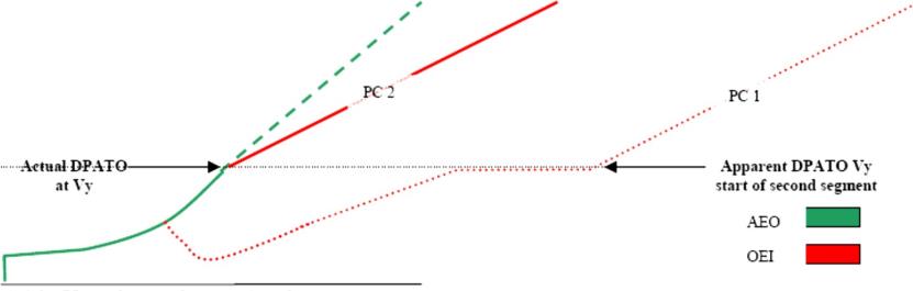
It is not necessary for specific AEO distances to be used (although for obvious reasons it is preferable); if they are not available, a flight path (with OEI obstacle clearance) can be established using Category A distances (see Figure 8 and Figure 9) — which will then be conservative.
Figure 8: Using Cat A data; actual and apparent position of DPATO (Vtoss and start of first segment)
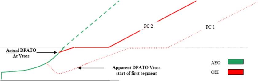
The apparent DPATO is for planning purposes only in the case where AEO data are not available to construct the take-off flight path. The actual OEI flight path will provide better obstacle clearance than the apparent one (used to demonstrate the minimum requirement) — as seen from the firm and dashed lines in the above figure.
Figure 9: Using Cat A data; actual and apparent position of DPATO (Vy and start of second segment)
(iii) Use of most favourable Category A data
The use of AEO data are recommended for calculating DPATO. However, where an AEO distance is not provided in the flight manual, distance to Vy at 200 ft, from the most favourable of the Category A procedures, can be used to construct a flight path (provided it can be demonstrated that AEO distance to 200 ft at Vy is always closer to the take-off point than the CAT A OEI flight path).
In order to satisfy the requirement of CAT.POL.H.315, the last point from where the start of OEI obstacle clearance can be shown is at 200 ft.
Safe forced landing areas should be available from the start of the take-off, to a distance equal to the Category A ‘clear area’ rejected take-off distance.
(iii) Third method
As an alternative, DPATO could be selected such that AFM OEI data are available to establish a flight path initiated with a climb at that speed. This speed should then be:
(A) one of the VTOSS values (or the unique VTOSS value if it is not variable) provided in the AFM, selected so as to assure a climb capability according to Category A criteria; or
(B) Vy
The height of the DPATO should be at least 35 ft and can be selected up to 200 ft. Compliance with CAT.POL.H.315 would be shown from the selected height.
(8) Safe forced landing distance
Except as provided in (f)(7)(ii), the establishment of the safe forced landing distance could be problematical as it is not likely that PC2 specific data will be available in the AFM.
By definition, the Category A reject distance may be used when the surface is not suitable for a reject, but may be satisfactory for a safe forced landing (for example, where the surface is flooded or is covered with vegetation).
Any Category A (or other accepted) data may be used to establish the distance. However, once established, it remains valid only if the Category A mass (or the mass from the accepted data) is used and the Category A (or accepted) AEO profile to the TDP is flown. In view of these constraints, the likeliest Category A procedures are the clear area or the short field (restricted area/site) procedures.
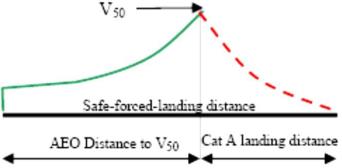
From Figure 10, it can be seen that if the Category B V50 procedure is used to establish DPATO, the combination of the distance to 50 ft and the Category A ‘clear area’ landing distance, required by CS/JAR 29.81 (the horizontal distance required to land and come to a complete stop from a point 50 ft above the landing surface), will give a good indication of the maximum safe-forced-landing distance required (see also the explanation on Vstayup above).
Figure 10: Category B (V50) safe–forced–landing distance
(9) Performance class 2 landing
For other than PC2 operations to elevated FATOs or helidecks (see section (g)(4)(i)), the principles for the landing case are much simpler. As the performance requirements for PC1 and PC2 landings are virtually identical, the condition of the landing surface is the main issue.
If the engine fails at any time during the approach, the helicopter must be able either: to perform a go-around meeting the requirements of CAT.POL.H.315; or perform a safe forced landing on the surface. In view of this, and if using PC1 data, the LDP should not be lower that the corresponding TDP (particularly in the case of a variable TDP).
The landing mass will be identical to the take-off mass for the same site (with consideration for any reduction due to obstacle clearance — as shown in Figure 6 above).
In the case of a balked landing (i.e. the landing site becomes blocked or unavailable during the approach), the full requirement for take-off obstacle clearance must be met.
(g) Operations in performance class 2 with exposure
The Implementing Rules offer an opportunity to discount the requirement for an assured safe forced landing area in the take-off or landing phase — subject to an approval from the CAA. The following sections deals with this option:
(1) Limit of exposure
As stated above, performance class 2 has to ensure AEO obstacle clearance to DPATO and OEI obstacle clearance from that point. This does not change with the application of exposure.
It can, therefore, be stated that operations with exposure are concerned only with alleviation from the requirement for the provision of a safe forced landing.
The absolute limit of exposure is 200 ft — from which point OEI obstacle clearance must be shown.
(2) The principle of risk assessment
ICAO Annex 6 Part III Chapter 3.1.2 states that:
‘3.1.2 In conditions where the safe continuation of flight is not ensured in the event of a critical engine failure, helicopter operations shall be conducted in a manner that gives appropriate consideration for achieving a safe forced landing.’
Although a safe forced landing may no longer be the (absolute) Standard, it is considered that risk assessment is obligatory to satisfy the amended requirement for ‘appropriate consideration’.
Risk assessment used for fulfilment of this proposed Standard is consistent with principles described in ‘AS/NZS 4360:1999’. Terms used in this text and defined in the AS/NZS Standard are shown in Sentence Case e.g. risk assessment or risk reduction.
(3) The application of risk assessment to performance class 2
Under circumstances where no risk attributable to engine failure (beyond that inherent in the safe forced landing) is present, operations in performance class 2 may be conducted in accordance with the non-alleviated requirements contained above — and a safe forced landing will be possible.
Under circumstances where such risk would be present, i.e. operations to an elevated FATO (deck edge strike); or, when permitted, operations from a site where a safe forced landing cannot be accomplished because the surface is inadequate; or where there is penetration into the HV curve for a short period during take-off or landing (a limitation in CS/JAR 29 AFMs), operations have to be conducted under a specific approval.
Provided such operations are risk assessed and can be conducted to an established safety target, they may be approved in accordance with CAT.POL.H.305.
(i) The elements of the risk management
The approval process consists of an operational risk assessment and the application of four principles:
(A) a safety target;
(B) a helicopter reliability assessment;
(C) continuing airworthiness; and
(D) mitigating procedures.
(ii) The safety target
The main element of the risk assessment when exposure was initially introduced by the JAA into JAR-OPS 3 (NPA OPS-8), was the assumption that turbine engines in helicopters would have failure rates of about 1:100 000 per flying hour, which would permit (against the agreed safety target of 5 x 10⁻⁸ per event) an exposure of about 9 seconds for twins during the take-off or landing event. (When choosing this target it was assumed that the majority of current well-maintained turbine powered helicopters would be capable of meeting the event target — it, therefore, represents the residual risk).
(Residual risk is considered to be the risk that remains when all mitigating procedures — airworthiness and operational — are applied (see sections (g)(3)(iv) and (g)(3)(v))).
(iii) The reliability assessment
The reliability assessment was initiated to test the hypothesis (stated in (g)(3)(ii) ) that the majority of turbine powered types would be able to meet the safety target. This hypothesis could only be confirmed by an examination of the manufacturers’ power-loss data.
(iv) Mitigating procedures (airworthiness)
Mitigating procedures consist of a number of elements:
(A) the fulfilment of all manufacturers’ safety modifications;
(B) a comprehensive reporting system (both failures and usage data); and
(C) the implementation of a usage monitoring system (UMS).
Each of these elements is to ensure that engines, once shown to be sufficiently reliable to meet the safety target, will sustain such reliability (or improve upon it).
The monitoring system is felt to be particularly important as it had already been demonstrated that when such systems are in place it inculcates a more considered approach to operations. In addition, the elimination of ‘hot starts’, prevented by the UMS, itself minimises the incidents of turbine burst failures.
(v) Mitigating procedures (operations)
Operational and training procedures, to mitigate the risk — or minimise the consequences — are required of the operator. Such procedures are intended to minimise risk by ensuring that:
(A) the helicopter is operated within the exposed region for the minimum time; and
(B) simple but effective procedures are followed to minimise the consequence should an engine failure occur.
(4) Operation with exposure
When operating with exposure, there is alleviation from the requirement to establish a safe forced landing area (which extends to landing as well as take-off). However, the requirement for obstacle clearance — AEO in the take-off and from DPATO OEI in the climb and en-route phases — remains (both for take-off and landing).
The take-off mass is obtained from the more limiting of the following:
— the climb performance of 150 ft/min at 1 000 ft above the take-off point; or
— obstacle clearance (in accordance with (f)(3) above); or
— AEO hover out of ground effect (HOGE) performance at the appropriate power setting. (AEO HOGE is required to ensure acceleration when (near) vertical dynamic take-off techniques are being used. Additionally, for elevated FATO or helidecks, it ensures a power reserve to offset ground cushion dissipation; and ensures that, during the landing manoeuvre, a stabilised HOGE is available — should it be required.)
(i) Operations to elevated FATOs or helidecks
PC2 operations to elevated FATOs and helidecks are a specific case of operations with exposure. In these operations, the alleviation covers the possibility of:
(A) a deck-edge strike if the engine fails early in the take-off or late in the landing;
(B) penetration into the HV Curve during take-off and landing; and
(C) forced landing with obstacles on the surface (hostile water conditions) below the elevated FATO (helideck). The take-of mass is as stated above and relevant techniques are as described in GM1 CAT.POL.H.310(c) & CAT.POL.H.325(c).
It is unlikely that the DPATO will have to be calculated with operations to helidecks (due to the absence of obstacles in the take-off path).
(ii) Additional requirements for operations to helidecks in a hostile environment
For a number of reasons (e.g. the deck size, and the helideck environment — including obstacles and wind vectors), it was not anticipated that operations in PC1 would be technically feasible or economically justifiable by the projected JAA deadline of 2010 (OEI HOGE could have provided a method of compliance, but this would have resulted in a severe and unwarranted restriction on payload/range).
However, due to the severe consequences of an engine failure to helicopters involved in take-off and landings to helidecks located in hostile sea areas (such as the North Sea or the North Atlantic), a policy of risk reduction is called for. As a result, enhanced class 2 take-off and landing masses together with techniques that provide a high confidence of safety due to:
(A) deck-edge avoidance; and
(B) drop-down that provides continued flight clear of the sea, are seen as practical measures.
For helicopters which have a Category A elevated helideck procedure, certification is satisfied by demonstrating a procedure and adjusted masses (adjusted for wind as well as temperature and pressure) that assure a 15-ft deck edge clearance on take-off and landing. It is, therefore, recommended that manufacturers, when providing enhanced PC2 procedures, use the provision of this deck-edge clearance as their benchmark.
As the height of the helideck above the sea is a variable, drop down has to be calculated; once clear of the helideck, a helicopter operating in PC1 would be expected to meet the 35-ft obstacle clearance. Under circumstances other than open sea areas and with less complex environmental conditions, this would not present difficulties. As the provision of drop down takes no account of operational circumstances, standard drop down graphs for enhanced PC2 — similar to those in existence for Category A procedures — are anticipated.
Under conditions of offshore operations, calculation of drop down is not a trivial matter — the following examples indicate some of the problems which might be encountered in hostile environments:
(A) Occasions when tide is not taken into account and the sea is running irregularly — the level of the obstacle (i.e. the sea) is indefinable making a true calculation of drop down impossible.
(B) Occasions when it would not be possible — for operational reasons — for the approach and departure paths to be clear of obstacles — the ‘standard’ calculation of drop-down could not be applied.
Under these circumstances, practicality indicates that drop down should be based upon the height of the deck AMSL and the 35-ft clearance should be applied.
There are, however, other and more complex issues which will also affect the deck- edge clearance and drop down calculations.
(C) When operating to moving decks on vessels, a recommended landing or take-off profile might not be possible because the helicopter might have to hover alongside in order that the rise and fall of the ship is mentally mapped; or, on take-off re- landing in the case of an engine failure might not be an option.
Under these circumstances, the commander might adjust the profiles to address a hazard more serious or more likely than that presented by an engine failure.
It is because of these and other (unforeseen) circumstances that a prescriptive requirement is not used. However, the target remains a 15-ft deck-edge clearance and a 35-ft obstacle clearance and data should be provided such that, where practically possible, these clearances can be planned.
As accident/incident history indicates that the main hazard is collision with obstacles on the helideck due to human error, simple and reproducible take-off and landing procedures are recommended.
In view of the reasons stated above, the future requirement for PC1 was replaced by the new requirement that the take-off mass takes into account:
— the procedure;
— deck-edge miss; and
— drop down appropriate to the height of the helideck.
This will require calculation of take-off mass from information produced by manufacturers reflecting these elements. It is expected that such information will be produced by performance modelling/simulation using a model validated through limited flight testing.
(iii) Operations to helidecks for helicopters with a maximum operational passenger seating configuration (MOPSC) of more than 19
The original requirement for operations of helicopters with an MOPSC of more than 19 was PC1 (as set out in CAT.POL.H.100(b)(2)).
However, when operating to helidecks, the problems enumerated in (g)(4)(ii) above are equally applicable to these helicopters. In view of this, but taking into account that increased numbers are (potentially) being carried, such operations are permitted in PC2 (CAT.POL.H.100(b)(2)) but, in all helideck environments (both hostile and non-hostile), have to satisfy, the additional requirements, set out in (g)(4)(ii) above.